IoT Radio Communication Attack – Part Three

This is the 3rd part in the series named "IoT – Radio Communication Attack." I hope you have read the first and second part, if not please go through it. I hope you have installed GNU Radio Companion (henceforth GRC) software on your laptop. Also, if you wish you can use Pentoo OS as discussed in the last post.
What we will learn - In this post, I will be explaining how to build an FM Radio receiver along with GRC and RTL-SDR.
Earn two pentesting certifications at once!
Enroll in one boot camp to earn both your Certified Ethical Hacker (CEH) and CompTIA PenTest+ certifications — backed with an Exam Pass Guarantee.
What is GRC - GRC is an open source software development toolkit which provides signal processing blocks for implementing SDR concepts. More info on GRC can be obtained here - https://wiki.gnuradio.org/index.php/What_is_GNU_Radio%3F, and for guided tutorials, please check - https://wiki.gnuradio.org/index.php/Guided_Tutorials.
It looks like this -

As seen above, it contains 3 main components -
- Workspace - Middle area where we see blocks like – Options and Variable.
- Blocks - One on the right side containing blocks like OFDM, WX GUI Notebook, FFT, and Graphical Sinks, etc.
- Reports - Bottom one which has the text "Welcome to GNU Radio Companion...."
Overview of FM signal demodulation - Suppose if you want to listen FM on your mobile. You start the FM application and tune it to a particular channel and listen to the song. However, what happens in the background?
There is a receiver in your mobile which receives the FM signal. The received signals are modulated signals and need to be demodulated first. It is like decrypting the encrypted data. Once they have been demodulated, the data should be passed on to the audio chip for playing the audio. The audio chip cannot play signal of any frequency. Standard frequencies supported are 16Khz,22.05Khz,24Khz,32Khz,44.1Khz and 48Khz. Thus, after demodulation, a signal of frequencies above should be passed to the audio chip for playing the song. If the passed signal is not one of the frequencies above, the audio chip will not be able to play the song and simply displays an error. Thus, the signal obtained after demodulation should be of the frequency mentioned above. I hope the process of playing the song is clear.
Plug in your RTL-SDR into one of the USB port. To check whether it has been detected, run rtl_test command and if you see the output as shown below, it means your RTL-SDR has been detected and is ready to use.
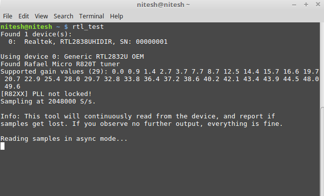
Stop the test by pressing Ctrl+C button.
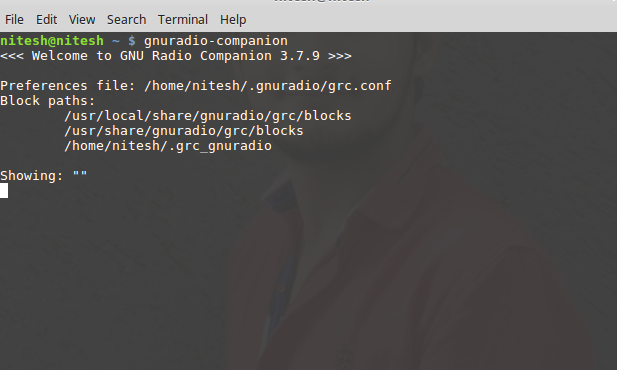
Now start the GRC using "gnuradio-companion" command as shown below -
GUI of GRC is shown below -
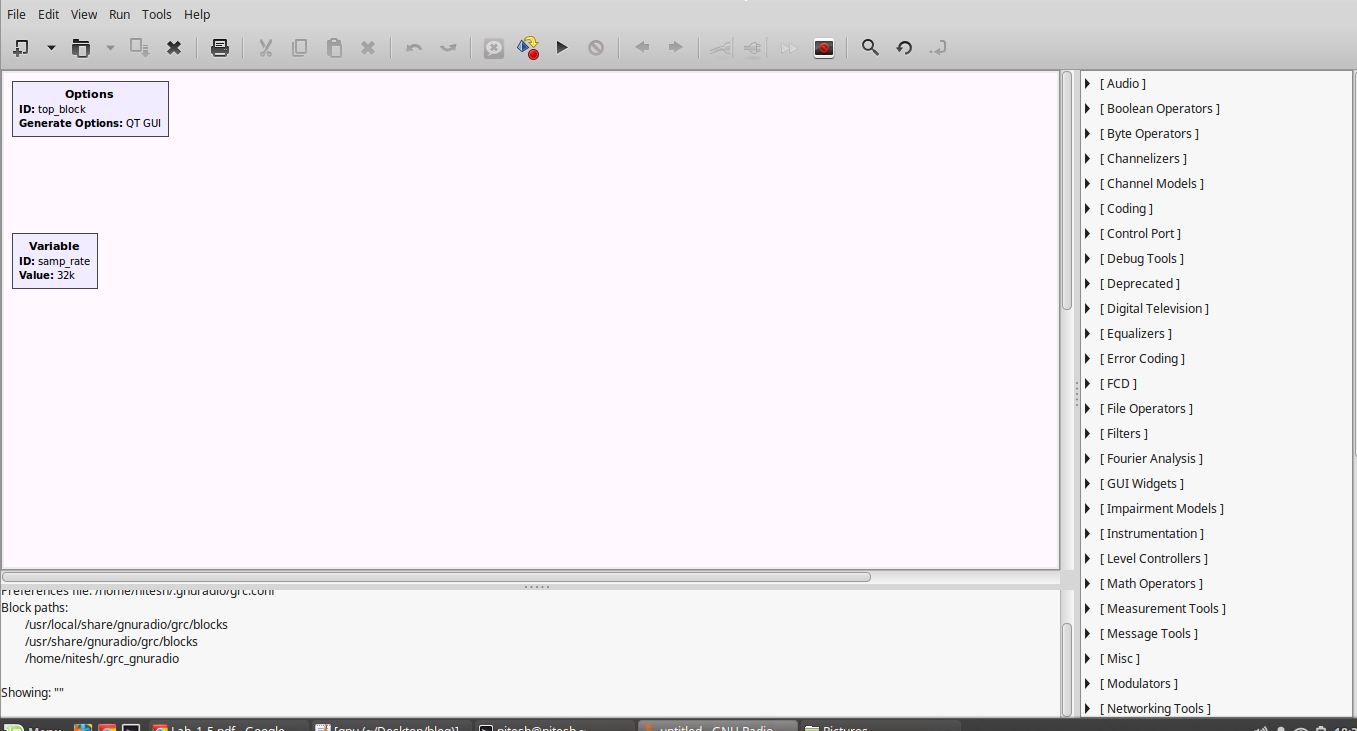
By default, it has 2 blocks - Options and Variable. In options, GUI is set to QT GUI and in Variable components - id is samp_rate, and the value for the sample rate is 32k, i.e., 32000. It is like declaring a variable in a programming language like a=20 where "a" is the id and 20 is the value of the variable. In our case, samp_rate is the variable and 32000 is the value of the variable. Double click on a samp_rate variable and change it to 1.5M, i.e., 15 lakhs.
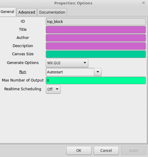
Double click on Options block and change the GUI to WX GUI as shown below -
To import a block, click on the search icon (blue color icon) and search for the particular block. Search for RTL-SDR source block and drag it into the workspace. If RTL-SDR source is not present in the GRC, please Google and get RTL-SDR source in GRC. As an alternative, you can use Pentoo OS for performing all the tasks as said above.
Thus, we have RTL-SDR source into the workspace as shown below -
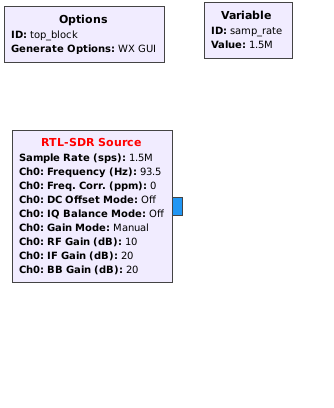
You may be wondering why to use RTL-SDR source. RTL-SDR will capture the FM signal, and the same is shown in GRC through RTL-SDR source. Thus, RTL-SDR source will provide the FM signal in GRC.
Double click on RTL-SDR source block and you should see the following values as shown below -
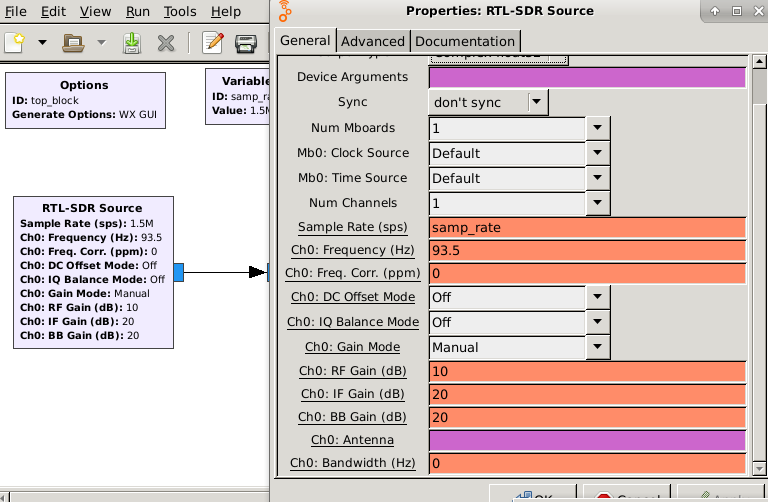
93.5 is the FM station for receiving the FM signal. In my country, 93.5 work fine. You can set the value according to your country. The sample rate is the value of the samp_rate variable. We have already declared a variable called samp_rate and have set it to value 1.5M, i.e., 15 lakhs. Thus, RTL-SDR will capture signals with sample rate 1.5M.
Similarly, import other blocks and build the graph with the value shown in the screenshot below -
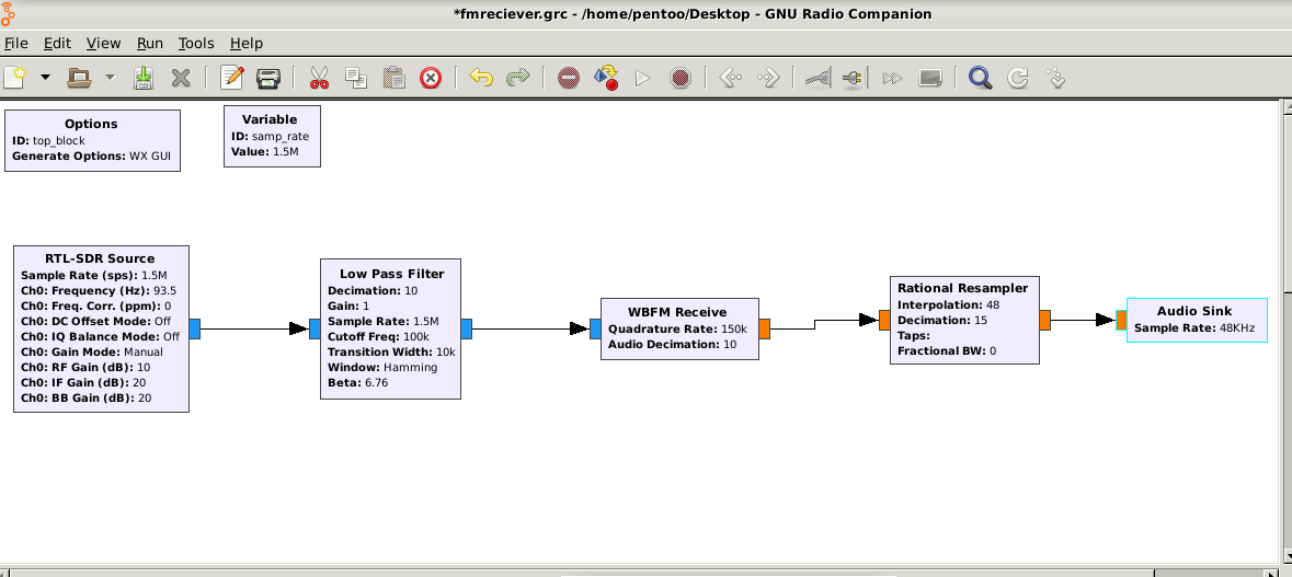
Let's have a look at the role of each block does and understand how it processes the signal.
Low pass Filter - RTL-SDR source will produce a signal of sample rate 1.5M. Processing signal of such a high sample rate involves too much of processing power. Thus, the sample rate must be decreased. We pass the output to low pass filter for modifying/processing the original signal. In low pass filter, the signal is decimated by 10 as shown. We often use a word such as decimation and interpolation. Decimation means dividing the signal and interpolation means multiplying the signal. Decimating the original signal, i.e., 1.5M/10 will produce signals with a sample rate of value 1.5 lakhs. Transition width is 10k, i.e., 10000 for eliminating the noise.
WBFM Receive - WBFM receive is used to demodulate the signal. It will demodulate the signal of sample rate 1.5 lakhs. In WBFM, we have Quadrature rate and Audio decimation. Quadrature rate is the sample rate of the received signal from low pass filters, i.e., 1.5 lakhs. Since we must pass this signal to audio chip, we decimate it by 10. Thus, the value of output signal is 150000/10 = 15000, i.e., 15k. Thus, WBFM will output the signal of value 15k. This value must be passed to audio chip.
Rational Resampler - Audio chip as said above can accept frequencies of specific values. In our case, we will pass the signal of frequency 48k i.e.48000 to the audio chip. Thus, we must convert the input signal of value 15000 to 48000.This is done using Rational Resampler. In Rational Resampler, we divide the signal by 15. This will give us output 1000 which when multiplied by 48 gives us 48000, i.e., 48k.Thus, Rational Resampler will produce the signal with frequency 48k.
Audio Sink – This block is responsible for playing the song. The output from Rational Resampler, i.e., a signal of frequency 48k is fed to the audio sink for playing the audio, i.e., data received from FM signal. This will play the song on our laptop.
So, this is how the FM signal can be demodulated in GRC. This gives us an idea of what happens in the background when we play the song in GQRX. I hope you have understood this if any doubts, please comment.
Now you are aware of the Digital Signal Processing and its concepts, in the next part, I will explain how to analyze the radio communication using some real IoT devices.
Stay Tuned.
References -
http://adammelton.com/RTL-SDR.html
Become a Certified Ethical Hacker, guaranteed!
Get training from anywhere to earn your Certified Ethical Hacker (CEH) Certification — backed with an Exam Pass Guarantee.
http://blog.opensecurityresearch.com/2012/06/getting-started-with-gnu-radio-and-rtl.html
Enroll in an Ethical Hacking Boot Camp and earn two of the industry’s most respected certifications — guaranteed.
- CEH exam voucher
- PenTest+ exam voucher
- Exam Pass Guarantee
- Live online hacking training
In this Series
- IoT Radio Communication Attack – Part Three
- The rise of ethical hacking: Protecting businesses in 2024
- How to crack a password: Demo and video walkthrough
- Inside Equifax's massive breach: Demo of the exploit
- Wi-Fi password hack: WPA and WPA2 examples and video walkthrough
- How to hack mobile communications via Unisoc baseband vulnerability
- How to build a hook syscall detector
- Top tools for password-spraying attacks in active directory networks
- NPK: Free tool to crack password hashes with AWS
- Tutorial: How to exfiltrate or execute files in compromised machines with DNS
- Top 19 tools for hardware hacking with Kali Linux
- 20 popular wireless hacking tools [updated 2021]
- 13 popular wireless hacking tools [updated 2021]
- Man-in-the-middle attack: Real-life example and video walkthrough [Updated 2021]
- Decrypting SSL/TLS traffic with Wireshark [updated 2021]
- Dumping a complete database using SQL injection [updated 2021]
- Hacking clients with WPAD (web proxy auto-discovery) protocol [updated 2021]
- Hacking communities in the deep web [updated 2021]
- How to hack Android devices using the StageFright vulnerability [updated 2021]
- Hashcat tutorial for beginners [updated 2021]
- How to hack a phone charger
- What is a side-channel attack?
- Copy-paste compromises
- Hacking Microsoft teams vulnerabilities: A step-by-step guide
- PDF file format: Basic structure [updated 2020]
- 10 most popular password cracking tools [updated 2020]
- Popular tools for brute-force attacks [updated for 2020]
- Top 7 cybersecurity books for ethical hackers in 2020
- How quickly can hackers find exposed data online? Faster than you think …
- Hacking the Tor network: Follow up [updated 2020]
- Podcast/webinar recap: What's new in ethical hacking?
- Ethical hacking: TCP/IP for hackers
- Ethical hacking: SNMP recon
- How hackers check to see if your website is hackable
- Ethical hacking: Stealthy network recon techniques
- Getting started in Red Teaming
- Ethical hacking: IoT hacking tools
- Ethical hacking: BYOD vulnerabilities
- Ethical hacking: Wireless hacking with Kismet
- Ethical hacking: How to hack a web server
- Ethical hacking: Top 6 techniques for attacking two-factor authentication
- Ethical hacking: Port interrogation tools and techniques
- Ethical hacking: Top 10 browser extensions for hacking
- Ethical hacking: Social engineering basics
- Ethical hacking: Breaking windows passwords
- Ethical hacking: Basic malware analysis tools
- Ethical hacking: How to crack long passwords
- Ethical hacking: Passive information gathering with Maltego
- Ethical hacking: Log tampering 101
- Ethical hacking: What is vulnerability identification?
- Ethical hacking: Breaking cryptography (for hackers)

Get certified and advance your career
- Exam Pass Guarantee
- Live instruction
- CompTIA, ISACA, (ISC)², Cisco, Microsoft and more!


