Reverse Engineering of Embedded Devices

Introduction
This article is for colleagues who are interested in studying the reverse engineering of embedded devices starting from the introduction of equipment that can be used to assist the process of reverse engineering. Communication protocols and interfaces are often used in embedded devices as well as some other important things. Reverse engineering of the embedded device itself aims to find out how it works, looking for possible but and the possibility of activating or adding features that found on the device
Tools of Trade
Here are some supplies that can help in the process of reversing embedding:
Learn Digital Forensics
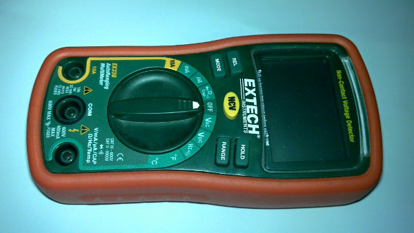
Multimeter
This tool is used to measure different types of currents including strong currents and voltage (AC / DC). There is also a feature to check the transistor. If you want to buy a multimeter, buy a digital an auto range multimeter, so you will not need to set more limits on what you want to measure. Professional multimeters are relatively expensive with brand names such as Fluke, Gossen, Agilent, and UNI-T. You do not need a professional multimeter, however, if you are a hobbyist, and are not doing this professionally. UNI-T and Extech make some good mid-grade multimeters.

Solder
Solder is used to connect components using lead solder. In the process of reversing embedded, sometimes we need to solder jumper wires or to remove components from the circuit board (PCB). There are various kinds of soldering, but you should use a solder that has a temperature regulator to facilitate the soldering process. For solder eyes, you should use as you needed, but keep in mind that the solder eye taper (sharp) is slower in delivering heat than flat solder eye (chisel). Similarly, if you use a lead-free solder (lead free), then you need a solder with a higher temperature than if you are using a regular soldering tin. However, can afford it, it is better to use a soldering station that has been equipped with a blower (solder steam) to make it easier if you have to deal with the components. Surface Mount Technology (SMT / SMD) is the electronic component mounting method is simply placed on the circuit board without having punching holes in the circuit board.
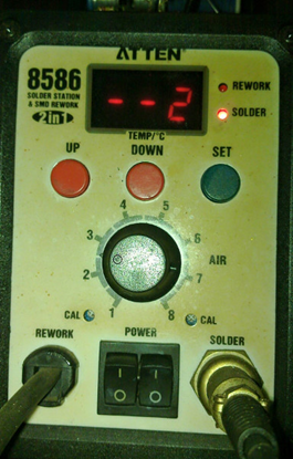
Figure 2:Hotgun solder
Tin Solder
There are two types of solder that are often used: tin lead-free solder (lead free), and tin solder that contains lead. Solder diameter varies with size. Typically, tin solder has a diameter of 0.8 mm. For daily needs, you can use the type 60/40 (60 percent lead, 40 percent lead) with a rosin core. In the middle, there is a rosin flux solder, which will give soldering process with better results. You can also buy rosin flux separately. This is helpful to the soldering process and is now available in a form that is easily dissolved in water (water-soluble flux) that helps the cleaning residue.
Solder Wick
Solder wick helps clean up the remnants of excessive solder or solder lifting of components so that electronic components can be lifted / removed easily from the circuit board (PCB). In addition to using solder wick, you can also use a vacuum, especially if you are working through whole components.
Bus Pirate
A bus pirate is a device that can be used to observe and interact using a variety of communication protocols commonly used by electronic devices, such as UART, SPI, and I2C. You can read the full documentation of the bus pirate on dangerous prototypes sites.
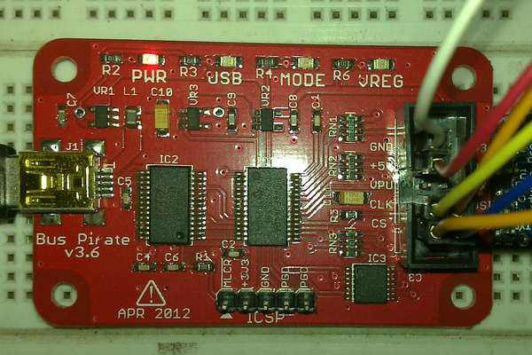
Figure 3: Bus Pirate V3.6
Oscilloscope
An oscilloscope is a device that can be used to observe changes in the signal in a certain period. The signal on the oscilloscope displays as a comparison of voltage with time. There are several types of oscilloscope in circulation. Initially, you can use a USB oscilloscope connected to your computer and using applications on the computer to display the signal. There is also a bench oscilloscope, an oscilloscope that has an integrated monitor.
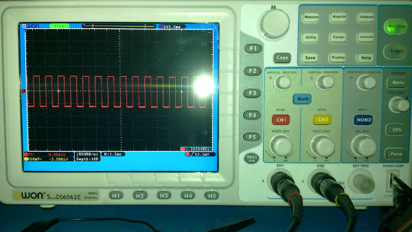
Figure 4: Oscilloscope
Logic Analyzer
The logic analyzer is used to analyze the logic signals on a digital system. The signal to be analyzed is first stored (capture / sampling), and it can be decoded according to the protocol used by the sample. The samples stored by the logic analyzer are sequential (uncompressed) and stored in their original condition, or compressed (compressed samples). To conduct sampling, use a logic analyzer trigger that will determine when to start capturing signals that will be used sample to be analyzed. There are two pieces of trigger modes used by the logic analyzer, timing mode and mode state. The commonly-used is one that uses a timing mode. Common logic analyzers include Saleae Logic, Open Bench Logic Sniffer, Asix Sigma2, USBee-SX and so forth. For front end client software, there are several alternatives options and this nature is open source such as OLS and Sigrok.
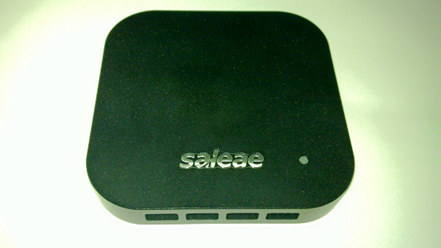
Figure 5: Saleae Logic Analyzer
JTAG Adapter
You can use the bus pirate as a JTAG adapter accompanied by OpenOCD. If you do not have a bus pirate, you can use other JTAG adapters for communication / debugging via JTAG protocol. There are many types of JTAG adapter that you can use such as GoodFET, JTAGulator, Die Datenkrake, Flyswatter2, and Bus Blaster. To understand more about JTAG, you can read in the form of a standard reference used is the IEEE 1149.1.
Binwalk (Software)
Binwalk is an open source application that can be used to analyze and extract the firmware contained on embedded devices. Firmware analysis conducted to find out the function that is often lacking in the documentation, including the possibility of backdoor applications that are inserted by the makers of embedded devices.
Flashrom (Software)
Flashrom is an open source application that can be used to read, write, and verify the data contained in the flash chip (EEPROM). Flash chips typically contain firmware, e.g. the BIOS chip on the computer. Flashrom itself is highly flexible and supports many types of flash chips and a variety of hardware programs, and can be used on multiple types of operating systems.
Datasheet
Datasheets contain information about a component and is usually accompanied by schematic that is recommended for such components. Datasheets are a source of very important information in the process of reversing embedded. As a simple example, a datasheet on an Integrated Circuit (IC) generally contains information about the function of each pin is on the IC. An IC has a pin for communication using serial, usually we can obtain information to facilitate debugging process of pin Tx (transmit) that exist in the IC by means of sniffing. Other pins are commonly used by the current IC is pin JTAG. Pin JTAG has many functions, such as for debugging, writing, extract the firmware inside the IC, and can be used to enumerate other components connected to the IC.
Other equipment
Other equipment that you should have: a set of screwdrivers, cutting pliers, nippers pliers, tweezers, magnifying glass, breadboard, jumper cables, a hot glue gun, LCR meter, frequency counter, dremel, and many other supporting devices. Moreover, you must to have knowledge of basic electronics, especially the function of discrete components such as transistors, resistors, capacitors and others, and knowledge of the architecture of the microcontroller / microprocessor that commonly used in embedded devices.
Protocols and Interface
UART/USART
UART / USART (Universal Asynchronous / Synchronous Receiver-Transmitter) are called a serial communication interface that is commonly found in embedded devices. Common protocols used in this interface are RS-232, and RS-485. There are two important signaling pathway that is used to communicate on this interface, such as:
- Tx (Transmit).As the name suggest, pin Tx (Transmit) Function to send data
- Rx (Receive). Pin Rx (Receive), function to receive data.
Communication speed on the UART interface is calculated using the unit baud is total number of signals per second, but in line with the changing times, the average device that uses a UART interface already has a feature to detect the baud rate automatically(automatic baud rate detection). Things to consider for protocol UART / USART: a connection between master and slave devices, Tx pin on the master connected with Rx pin on the slave, Tx pin on the slave connected to the Rx pin on the device that functions as a master. Now, serial communication in embedded devices generally use between serial and USB adapter, and the IC is commonly used as the adapter is made in FTDI, eg FT232 series
SPI
SPI or Serial Peripheral Interface is a communication protocol that is widely used by electronic devices besides UART. SPI protocol can connect multiple peripherals, which serves as a master peripheral and other peripherals to function as a slave. The connection between master and slave uses lines SCLK, the same of MISO and MOSI, but the path is different CS for each peripheral. This communication protocol uses four pieces of the path for the signal. These pathways are:
- SCLK (Serial Clock) is the path used by the master device to generate a clock that will be used to regulate the flow of data when there is communication between master and slave devices.
- MISO (Master In Slave Out) grooves are used to transmit data from the slave device to the master device.
- MOSI (Master Out Slave In) a path used to transmit data from the master device to the slave device.
- SS (Slave Select) / CS (Chip Select) function to enable slave peripherals that want to communicate with the master and disable other peripherals that are not used. However, there are conditions where it does not work that way. It is caused by the slave output lines (MISO) is not equipped with a tri-state logic.
I 2 C
I 2 C (Inter Integrated Circuit) is a protocol that was discovered by Philips Semiconductor (now NXP). This protocol is often called the TWI (Two Wire Interface) because the first name I 2 C is a patent from NXP. The advantage of this protocol is because it only requires two signal paths for data transmission, that is:
-
SCL (Serial Clock Line). Device that serve as master function to generate a clock to be transmitted through the SCL (Serial Clock Line) while on duty as a slave device function receives a clock from the master and then provide a response in the form to receive or send data.
-
SDA (Serial Data Line) is the path used for data exchange between master and slave devices.
As with SPI, several devices can be connected using the I 2 C protocol, and the limit is the maximum number of addresses connected devices and total capacitance of the connection between devices is 400pF.
Common devices using I 2 C communication protocol are EEPROM, sensor IMU (Inertial Measurement Unit), Real Time Clock (RTC) and others.
JTAG
JTAG is an electronic component testing method, regulated by the IEEE 1149.1 standard and was originally a recommendation by a group of manufacturers of electronic components incorporated in the Joint Test Action Group. The advantage of JTAG is its ability to perform testing of electronic components without direct physical contact with the pin you want to change or read the value. It is extremely important, given the current electronic components' smaller size with a pin which is very difficult to reach, such as pin contained on components that use BGA packaging / WLCSP. JTAG interface known as the Test Access Port (TAP), and the following is a signaling pathway that is used by the interface:
Protocols and interfaces described above are only part of the protocol contained on embedded devices. There are still many other protocols and interfaces that you can learn, such as Inter Integrated Circuit Sound (I 2 S) that is used for audio signals, Serial Wire Debug (SWD) is a protocol developed by ARM, Spy-Bi-Wire (SBW) developed by Texas Instruments, Camera Serial Interface (CSI) Digital Serial Interface (DSI) developed by the MIPI Alliance, CANBUS which is mostly used in vehicles, Low Voltage Differential Signalling (LVDS) are typically used on the LCD display, for example, and others.
Hardware Information
Before performing reverse embedded, we must know first the information chip that is used by that embedded. Here is information from some of the chips that are used by broadcasters' livestream along with their respective functions:
Ogemray GWF-3E
Wireless module (wireless) artificial 2.4GHz Shenzen Ogemray Technology Co., Ltd. This module uses the Ralink RT3070 chip with a peak rate of 150Mbps and 27Mbps peak throughput and is equipped with a built-in-PCB antenna and power management. The standard used was 802.11 B / G / N and the connection to the device using the USB.
Maxim MG3500A3-376B
1920x1080i HD H.264 Codec Chip SoC (System on Chip) is for handling multimedia processing such as images and sounds. This chip is ARM9-based and equipped with two real-time programmable multimedia engines (MME), respectively for processing images and audio.
Analog Devices ADV7611
This chip serves as the input from HDMI processor and operates with a frequency of 165MHz. Examples of the input is from the camera.
SMSC USB2513B
This chip functions as a USB hub controller that regulates all aspects related to the USB connection on the device livestream broadcaster.
Samsung K4T51163QJ-BCE6
This is chip DDR2 SDRAM made by Samsung.
Micron MT29F2G08ABAEAWP-IT
This is a 2 GB NAND chip that serves as storage media OS / firmware livestream broadcaster.
How Livestream Works

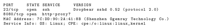
When livestream broadcaster is active, it will automatically attempt to connect to the internet. Users' livestream broadcaster was given several options for connection, which uses Ethernet, WiFi or USB modem. Users also can set the IP address of the device manually if they do not want to use DHCP. After connecting to the server livestream, the device will display the URL livestream broadcaster that should be accessed by the user to enter a PIN displayed on the device screen livestream broadcaster. In addition, the device also livestream broadcaster there are 2 open TCP port is port 22 and port 8080, as can be seen in pieces using nmap scan results the following:
Especially for port 22, can be seen that the service is run is SSH. Although we can connect to the port, we will have a public key problem that we have to be on the livestream broadcaster.
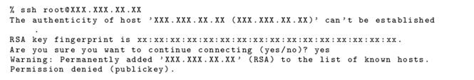 Figure 7: Ssh connection
As for the port 8080, as of this writing, it is an unknown function. Although in general the port functions as a web proxy, but after going through some testing, these ports do not respond at all.
Serial connection
Board livestream broadcaster has a 6 piece pin located between the power socket and HDMI port. However, this pin has only minimal information written on DB1, so we must try to find its own the function of each pin. If we observe, the 6 piece pins are somewhat similar to serial UART pins on the ubnt routerstation. For more details, we will use a multimeter to find the pin that serves as Gnd, Tx and Rx. The trick is to turn the power on livestream broadcaster, and the first to look for is the pin that serves as ground. To search for a pin that serves as a ground, just look for the part that is open and has a conductor on board livestream broadcaster and touch with one connector multimeter. Then with another multimeter connector, start looking for one by one pin serial that has a resistance value of 0.
You will see that most of the pins are located in the board livestream broadcaster serves as a Gnd. Next seek for pin Tx / Rx, connect one multimeter on pin connector Gnd obtained in the previous step. The other connector is used to test one by one from the fifth pin remaining. Touch one by one pin with a multimeter connector others. Tx pin usually has a 1.8v or 2.8v voltage value and the value Rx pin 1.7V or 2.7V. This information was obtained from one gsm forum on the internet. After doing some tests, finally pin Tx and Rx can be found with the same configuration with pin serial contained on ubnt routerstation board. Here is information on the serial pins on the device livestream broadcaster:
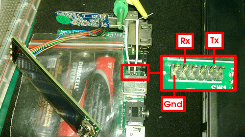
Figure 8: Inside the Hardware Livestream
Serial Log
After finding the Tx and Rx pin on the device livestream broadcaster, then we can connect to a computer using a serial adapter. For this article, we used the bus pirate v3.6. Because the location of the pins on the device livestream broadcaster is sufficiently tight, and difficult to reach by the connector hook, we used additional cables. There is a difference when a serial connection with the livestream broadcaster which LCD panels are being installed and when the LCD panel is not attached.
When the LCD panel is being installed, the input is entered to stop the boot process will only make the livestream broadcaster reboot. Whereas if the LCD panel is not attached. So the boot process will run using verbose function before we finally encounter an error. The message that appears when an error occurs shows much information about the device livestream broadcaster. Here is a snippet error messages that provide information regarding the location of the program counter (PC) when an error

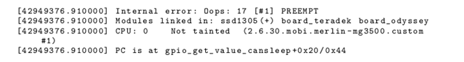
From information on the above, it can be seen that it is possible that the device livestream broadcaster is similar to the Teradek device VidiU and confirmed with the following information written on teradek sites:
VidiU is certified by Ustream and the new Livestream platforms, but also includes a generic RTMP interface that enables streaming to any other platform on the Web.
For more details, here is a message that appears when the device livestream broadcaster boot processes without LCD panel:

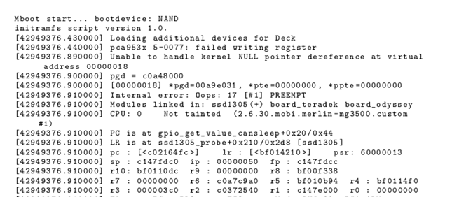
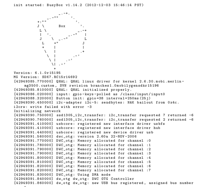
Figure 11: Boot Processing 2
from information obtained from the boot processing has information such as the names of the hardware used.
Learn Digital Forensics
Conclusion
From some of the information obtained from reversing livestream above, someone could only learn about the hardware through information obtained from the chip (look for the datasheet) and the possibility to inject malware into the hardware, it can detect even the possibility of backdoor that had been installed.

In this Series
- Reverse Engineering of Embedded Devices
- Digital forensics and cybersecurity: Setting up a home lab
- Top 7 tools for intelligence-gathering purposes
- iOS forensics
- Kali Linux: Top 5 tools for digital forensics
- Snort demo: Finding SolarWinds Sunburst indicators of compromise
- Memory forensics demo: SolarWinds breach and Sunburst malware
- Digital forensics careers: Public vs private sector?
- Email forensics: desktop-based clients
- What is a Honey Pot? [updated 2021]
- Email forensics: Web-based clients
- Email analysis
- Investigating wireless attacks
- Wireless networking fundamentals for forensics
- Protocol analysis using Wireshark
- Wireless analysis
- Log analysis
- Network security tools (and their role in forensic investigations)
- Sources of network forensic evidence
- Network Security Technologies
- Network Forensics Tools
- The need for Network Forensics
- Network Forensics Concepts
- Networking Fundamentals for Forensic Analysts
- Popular computer forensics top 19 tools [updated 2021]
- 7 best computer forensics tools [updated 2021]
- Spoofing and Anonymization (Hiding Network Activity)
- Browser Forensics: Safari
- Browser Forensics: IE 11
- Browser Forensics: Firefox
- Browser forensics: Google chrome
- Webinar summary: Digital forensics and incident response — Is it the career for you?
- Web Traffic Analysis
- Network forensics overview
- Eyesight to the Blind – SSL Decryption for Network Monitoring [Updated 2019]
- Gentoo Hardening: Part 4: PaX, RBAC and ClamAV [Updated 2019]
- Computer forensics: FTK forensic toolkit overview [updated 2019]
- The mobile forensics process: steps and types
- Free & open source computer forensics tools
- An Introduction to Computer Forensics
- Common mobile forensics tools and techniques
- Computer forensics: Chain of custody [updated 2019]
- Computer forensics: Network forensics analysis and examination steps [updated 2019]
- Computer Forensics: Overview of Malware Forensics [Updated 2019]
- Incident Response and Computer Forensics
- Computer Forensics: Memory Forensics
- Comparison of popular computer forensics tools [updated 2019]
- Computer Forensics: Forensic Analysis and Examination Planning
- Computer forensics: Operating system forensics [updated 2019]
- Computer Forensics: Mobile Forensics [Updated 2019]
- Computer Forensics: Digital Evidence [Updated 2019]

Get certified and advance your career
- Exam Pass Guarantee
- Live instruction
- CompTIA, ISACA, (ISC)², Cisco, Microsoft and more!

Digital forensics

Digital forensics

Digital forensics
Digital forensics