IoT Radio Communication Attack - Part 1 – Digital Signal Basics and Theory

This is the first post in the series named "IoT - Radio Hacking." This is a large topic and to make it digestible I will break it into multiple articles.
What I wish to cover in the series – Internet of things – IoT, we all have heard about IoT, right?
Earn two pentesting certifications at once!
Enroll in one boot camp to earn both your Certified Ethical Hacker (CEH) and CompTIA PenTest+ certifications — backed with an Exam Pass Guarantee.
IoT stands for Internet of Things. Using IoT technology each and everything, i.e., Car, Buildings, Fan, Bulb, Microwave Oven, etc. will be connected to the internet for sharing and exchanging the data.
Next question which should come to your mind is - How these devices will be connected to each other?
Either using some form of wired connection or wireless connection. Connecting these devices using some wire is not feasible because of infrastructure cost, space, and maintenance involved in connecting the devices using wires. Thus, these devices will be connected wirelessly and share and exchange data with each other wireless. Also, wireless connection does not involve much cost and does not occupy space. Thus, the wireless connection is the preferred way of connecting various IoT devices. When I say wireless connection, I mean these devices will use some wireless protocols such as ZigBee, RFID, and Bluetooth, etc. For certain tasks like unlocking the car door, these protocols are not used. Instead, some form of radio communication is used. Through the radio communication, some data is transmitted by the transmitter, and the transmitted data is received by the receiver. The data being sent is modulated first by the transmitter and is demodulated at the receiver end by the receiver.
To ensure the security of IoT infrastructure, all the components involved in the infrastructure should be secure. Radio communication is one of them. If one has a look at the history of radio communication security, many vulnerabilities have been discovered and exploited in IoT devices using some sort of Radio communication. Thus, for attacking the radio communication one should have a strong understanding of how IoT devices communicate over radio channels and what all different modulation schemes they use. Once the modulation scheme has been identified, we have to demodulate the original signal and extract the data present in the signal. To do so, some background and basics of Digital Signal Processing is required, which I will cover in the initial part of this series.
Let's start.
Electromagnetic Waves – Majority of IoT device use wireless communication. Example – Using remote for locking the car. For wireless communication, they use waves to communicate with each other. These waves are called Electromagnetic Waves (henceforth EV). EV can be Radio waves, X-rays, Microwaves, etc. On what basis the Electromagnetic waves are classified into different types?
"FREQUENCY"
Yes,
based on Frequency, Electromagnetic waves are classified into different types. More on Frequency will be covered in the upcoming part.
So, based on frequency, EV can be Radio waves, X-rays, Microwaves, etc.
If the frequency of the wireless communication is in the range of 3 KHz - 300 GHz, then it is termed as Radio Wave communication, and the waves are Radio Waves.
All the IoT device use Radio Waves for wireless communication.
Radio Communication Theory and Terminology –
1. Frequency - Frequency is the number of cycles completed in each time duration. Time duration can be seconds, minutes, etc.

As shown above, the Frequency of the radio wave is 3 cycles per second. The unit of frequency is the Hertz. It is denoted as Hz. As shown above, the frequency is 3 Hz, i.e., 3 Hertz.
Frequencies for Radio Waves are described in multiples of hertz –
- KHz or kilohertz - thousand cycles per second.
- MHz or megahertz - million cycles per second.
- GHz or gigahertz - billion cycles per second.
2. Wavelength - The distance between the two consecutive high points (high peaks) or troughs (low peaks) in a radio wave is termed as the wavelength. Wavelength is denoted as lambda (λ)

As shown above, the distance between the two consecutive high points (high peaks) is the wavelength of the radio wave.
3. Amplitude - The maximum height from the origin or starting position which a wave attains is known as amplitude. The definition may not be clear but if you have a look at the diagram shown below you will come to know what amplitude is -

4. Phase – The position of a single point on the wave is called as a phase. The unit for the phase is degree or radians.

As seen above, the phase can be 0, 90,180 degrees.
5. Transmitter – A device which can generate and transmit the radio wave is termed as Transmitter.
6. Receiver - A device which can receive the radio wave is termed as Receiver.
7. Transceiver – A device which can send and receive the radio waves is called as Transceiver.
8. Modulation and Demodulation Concepts – Modulation and demodulation involves the following concepts -
a. Carrier Waves – I have explained you the basics of radio waves. Now what we must do is – transmit the information to the destination in the form of radio waves. How can one do it?
For this, carrier waves come into the picture. Carrier waves as the name suggests are responsible for carrying the data/information to the destination. Thus, using carrier wave one can send our data to the destination.
b. Modulation – Modulation is the process of mixing the data into the carrier wave so that it can be transmitted to the destination. Modulation is achieved by varying the amplitude or frequency or phase of the carrier wave.
Depending on what is varied there are different types of modulation such as frequency modulation, amplitude modulation, phase modulation and so on.
9. Modulation Schemes – Modulation schemes can be divided into analog or digital modulation.
I.
Analog Modulation are of following types –
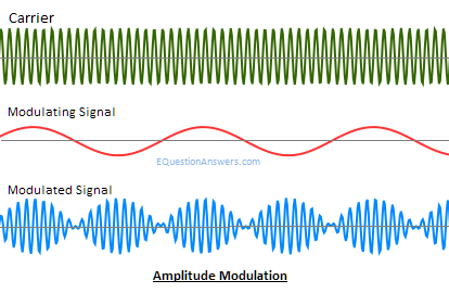
a) Amplitude Modulation (AM) – If the amplitude of the carrier signal is changed according to the amplitude of the data signal then it is known as Amplitude Modulation. This can be seen in the diagram below –

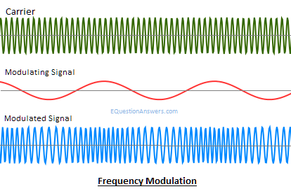
b) Frequency Modulation (FM) – If the Frequency of the carrier signal is changed according to the frequency of the data signal then it is known as Frequency Modulation. This can be seen in the diagram below –

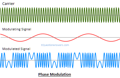
c) Phase Modulation (PM) – If the phase of the carrier signal is changed according to the phase of the data signal then it is known as Phase Modulation. This can be seen in the diagram below –

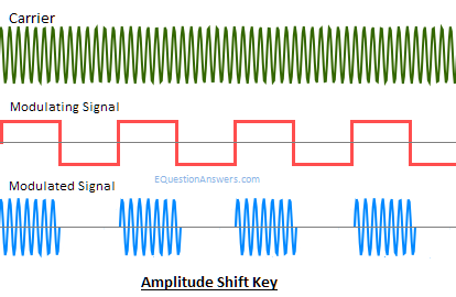
II. Digital Modulation – In Digital Modulation we have 2 levels – either high (logic 1) or low (logic low). Like analog modulation, the types of digital modulation are of following types –
a) ASK or Amplitude Shift Keying – If the amplitude of the carrier wave varies in accordance with the data signal, then it is called as Amplitude Shift Keying. Since Amplitude Shift Keying is digital modulation, if the data is present it will be shown as 1 else it will be shown as 0. Hence, Amplitude shift Keying is also called as on-off keying.

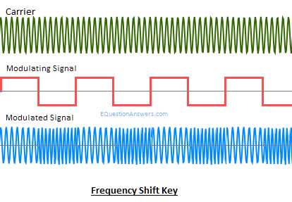
b) FSK or Frequency shift keying – If the frequency of the carrier wave varies in accordance with the data signal, then it is called as Frequency Shift Keying. The frequency of the carrier in FSK modulation changes as shown below –

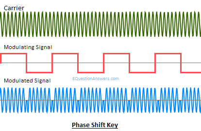
c) PSK or Phase shift keying – It is also called as BPSK. If the phase of the carrier wave varies in accordance with the data signal, then it is called as Phase Shift Keying. The phase of the carrier wave in PSK modulation changes as shown below –

Above mentioned modulation schemes are widely used. Apart from it, other complex modulation schemes are also used which I will cover when we come across it.
As of now, this much of theory is more than enough for getting started with the Radio Communication Hacking. In the next part, I will explain what all Software's and Hardware's are used for attacking the radio communication. Also, I will show a small demo of the tools for hands-on practice and to understand how to use a particular tool.
That's it for this part. If you have any doubt, please comment
Image Sources –
http://itlaw.wikia.com/wiki/frequency
http://cdn.ttgtmedia.com/whatis/images/waveleng.gif
https://physics.stackexchange.com
http://www.equestionanswers.com/notes/images/amplitude-modulation-waves.png
http://www.equestionanswers.com/notes/images/frequency-modulation-waves.png
http://www.equestionanswers.com/notes/images/phase-modulation-waves.png
http://www.equestionanswers.com/notes/images/amplitude-shift-key.png
http://www.equestionanswers.com/notes/images/frequency-shift-key.png

FREE role-guided training plans
http://www.equestionanswers.com/notes/images/phase-shift-key.png

- 12 pre-built training plans
- Employer-requested skills
- Personalized, hands-on training
In this Series
- IoT Radio Communication Attack - Part 1 – Digital Signal Basics and Theory
- The rise of ethical hacking: Protecting businesses in 2024
- How to crack a password: Demo and video walkthrough
- Inside Equifax's massive breach: Demo of the exploit
- Wi-Fi password hack: WPA and WPA2 examples and video walkthrough
- How to hack mobile communications via Unisoc baseband vulnerability
- How to build a hook syscall detector
- Top tools for password-spraying attacks in active directory networks
- NPK: Free tool to crack password hashes with AWS
- Tutorial: How to exfiltrate or execute files in compromised machines with DNS
- Top 19 tools for hardware hacking with Kali Linux
- 20 popular wireless hacking tools [updated 2021]
- 13 popular wireless hacking tools [updated 2021]
- Man-in-the-middle attack: Real-life example and video walkthrough [Updated 2021]
- Decrypting SSL/TLS traffic with Wireshark [updated 2021]
- Dumping a complete database using SQL injection [updated 2021]
- Hacking clients with WPAD (web proxy auto-discovery) protocol [updated 2021]
- Hacking communities in the deep web [updated 2021]
- How to hack Android devices using the StageFright vulnerability [updated 2021]
- Hashcat tutorial for beginners [updated 2021]
- How to hack a phone charger
- What is a side-channel attack?
- Copy-paste compromises
- Hacking Microsoft teams vulnerabilities: A step-by-step guide
- PDF file format: Basic structure [updated 2020]
- 10 most popular password cracking tools [updated 2020]
- Popular tools for brute-force attacks [updated for 2020]
- Top 7 cybersecurity books for ethical hackers in 2020
- How quickly can hackers find exposed data online? Faster than you think …
- Hacking the Tor network: Follow up [updated 2020]
- Podcast/webinar recap: What's new in ethical hacking?
- Ethical hacking: TCP/IP for hackers
- Ethical hacking: SNMP recon
- How hackers check to see if your website is hackable
- Ethical hacking: Stealthy network recon techniques
- Getting started in Red Teaming
- Ethical hacking: IoT hacking tools
- Ethical hacking: BYOD vulnerabilities
- Ethical hacking: Wireless hacking with Kismet
- Ethical hacking: How to hack a web server
- Ethical hacking: Top 6 techniques for attacking two-factor authentication
- Ethical hacking: Port interrogation tools and techniques
- Ethical hacking: Top 10 browser extensions for hacking
- Ethical hacking: Social engineering basics
- Ethical hacking: Breaking windows passwords
- Ethical hacking: Basic malware analysis tools
- Ethical hacking: How to crack long passwords
- Ethical hacking: Passive information gathering with Maltego
- Ethical hacking: Log tampering 101
- Ethical hacking: What is vulnerability identification?
- Ethical hacking: Breaking cryptography (for hackers)

Get certified and advance your career
- Exam Pass Guarantee
- Live instruction
- CompTIA, ISACA, (ISC)², Cisco, Microsoft and more!


