Introduction to Smartcard Security

Introduction
In 1968 and 1969, the smartcard was patented in German by Helmut Gröttrup and Jürgen Dethloff. The smartcard is simply a card with an Integrated Circuit that could be programmed. This technology has been used widely in our daily lives and will become one of the important keys in Internet of Things (IoT) and Machine to Machine (M2M) technology. Smartcard applications could be programmed using Java Card, an open platform from Sun Microsystems. Today, we find smartcard technology mostly used in communications (GSM/CDMA Sim Card) and payments (credit/debit card). This is an example of smartcard technology that has been used in Indonesia:

FREE role-guided training plans
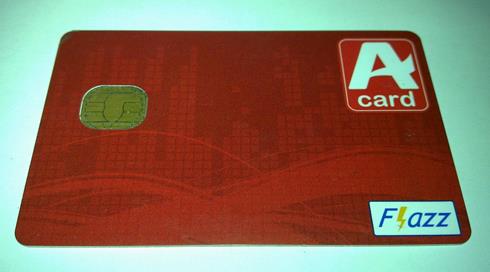
Picture 1. EMVd ebit card.
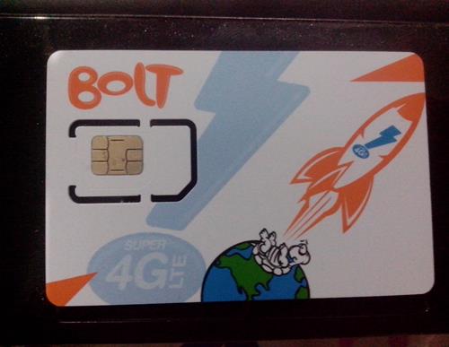
Picture 2. Bolt 4G card.
Smartcard Architecture
Picture 3. Smartcard architecture (image courtesy of THC)
How Does the Smartcard Work?
1. Smartcard Activation
In order to interact with the smartcard that has been connected to a smartcard terminal, it should be activated using electrical signals according to smartcard specification class A, B, or C (ISO/IEC 7816-3). The activation sequence goes like this:
More detailed information about this smartcard activation (before timing Ta) can be seen in this picture:
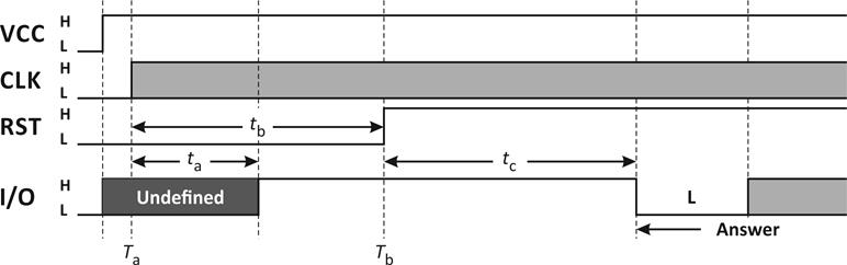
Picture 4. Smartcard activation and cold reset.
2. Cold Reset
At the end of activation (RST pin pulled to LOW, Vcc pin has been powered, I/O on smartcard terminal has been put to receive mode and CLK pin supplied a stable clock signal), then the smartcard is ready to enter Cold Reset.
As you can see from the above picture, the clock signal at the CLK pin starts at Ta and the smartcard will set the I/O signal to HIGH in 200 clock cycle (ta delay) after the clock signal is applied to CLK pin (Ta + ta). The RST pin should be kept in LOW state for at least 400 clock cycles (tb delay) after clock signal has been given to CLK pin (Ta + tb). The smartcard terminal could ignore the logic in I/O pin when RST pin is on LOW state.
RST pin then change to HIGH state after reaching Tb. I/O pin will begin the Answer-to-Reset from 400 to 40000 clock cycle (tc delay) after rising edge signal in RST pin (Tb + tc). If there is no answer after the 40000 clock cycle when the RST pin is in HIGH state, then the smartcard terminal could deactivate the smartcard.
3. Smartcard ATR (Answer-to-Reset)
After the smartcard performs a cold reset, then it will continue with Answer-to-Reset (ATR). The complete ATR structure is covered in ISO/IEC 7816-3, and it looks like this:
TS T0 TA1 TB1 TC1 TD1 TA2 … … TDn T1 … TK TCK
For example, this is the Answer-to-Reset that we receive after performing a cold reset on a smartcard:
3B BE 94 00 40 14 47 47 33 53 33 44 48 41 54 4C 39 31 30 30
After receiving the ATR above, we then continue with interpreting the data as follows:
It means that the smartcard operates using direct convention that works almost like UART protocol. The direct convention operation was covered in ISO/IEC 7816-3.
- High nibble (B16 = 10112) means that there is a data on TA1, TB1, dan TD1.
- Low nibble (E16 = 1410) means that there is 14 bytes of history data (TK).
- High nibble (916 = 10012) means that the clock rate is Fi = 512 with fmax = 5 MHz.
- Low nibble (416 = 01002) means that bit rate Di = 8.
According to ISO/IEC 7816-3, the TB1 and TB2 has been deprecated and not used anymore so the smartcard doesn't have to transmit it and the smartcard terminal could just ignore it.
- High nibble (416 = 01002) means that TC2 contains data.
- Low nibble (016 = 00002) means that the smartcard is using T = 0 protocol.
This is the Waiting Time Integer (WI) with a value of 20. From the ISO/IEC 7816-3, the value could be used to calculate Waiting Time (WT) with this formula:
This could be converted to ASCII : G G 3 S 3 D H A T L 9 1 0 0
4. Protocol and Parameter Selection Interface (PPS)
After getting Answer-to-Reset (ATR), the smartcard interface then could send PPS instruction to choose which protocol and parameter it would use to make data transfer between the smartcard and the terminal easier.
5. Data Transfer Between Smartcard and Terminal
After the Protocol and Parameter Selection (PPS) has been setup, the smartcard and the terminal interface could begin transferring data using Application Protocol Data Unit (APDU). The complete structure for APDU is covered in ISO 7816-4.
Vulnerabilities
There are quite a lot of vulnerabilities related to the java card, and most of them have been documented across the Internet. This is some of the smartcard's attack vector:
1. Physical attack:
-
Reverse engineering.
-
Smartcard cloning.
2. Remote attack:
-
IMSI catcher.
Attacking a Smartcard
1. Physical Attack
Physical attack could be carried out if the attacker has physical contact with victim's smartcard and gets access to important data on the smartcard. Once the attacker has access to that important data, he/she could perform a smartcard cloning or reprogramming of the smartcard.
1.1. Reverse Engineering
Picture 5. Typical smartcard front side.
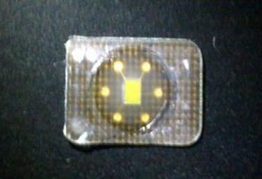
Picture 6. Typical smartcard back side.

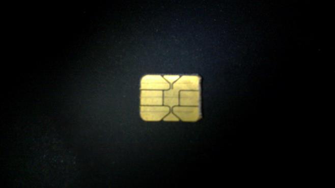
Picture 7. Smartcard IC "die"
Reverse engineering smartcard at silicon level is not an easy task and requires some special tools such as Scanning Electron Microscope (SEM) and/or Focused Ion Beam (FIB).
1.2. Smartcard Cloning
For this purpose, an attacker could use a couple of devices like an oscilloscope and smartcard reader. This is an example of DIY smartcard reader (phoenix reader):
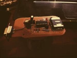
Picture 8. DIY smartcard reader (phoenix reader).
However, there's a catch for the phoenix reader like the one in the above picture – its lack of application for interfacing with smartcard. The reference schematic for phoenix reader used in the above picture was developed by Dejan Kaljevic and is freely available.
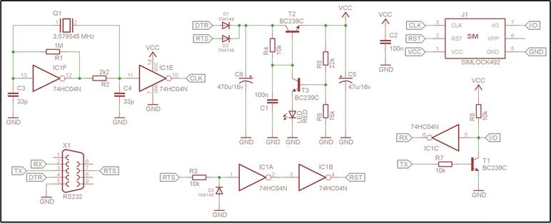
Picture 9. Phoenix reader schematic.
Smartcard cloning is not just about programming the smartcard, but also retrieving important information about the victim's smartcard such as which vendor issued the card. The more convenient way to interact with the smartcard is by using PCSC reader with an opensource application called pcsc_scan. This is an example of pcsc_scan usage:
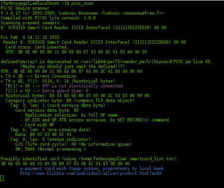
Picture 10. Information retrieved from smartcard payment.
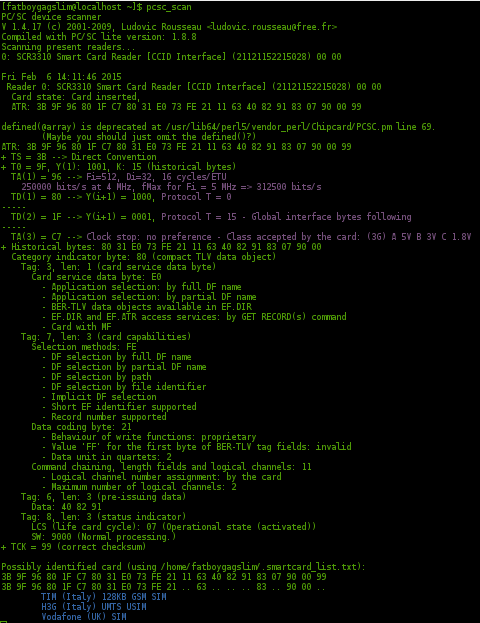
Picture 11. Information from 3G/4G smartcard.
As you may see in the picture above, we could get some information from the smartcard attached to the terminal. Picture 10 shows a smartcard that's commonly used in a financial institution which complies with the EMV standard, and picture 11 shows a smartcard (USIM) that's commonly used for communication (3G/4G). That information could be used to determine what kind of encryption the smartcard uses, since vendors tends to follow standard specs and not use custom encryption. Attackers could then use the information to perform a remote attack.
2. Remote Attack
Remote attacking smartcard could be achieved by exploiting vulnerabilities in the smartcard. For example; by injecting malicious "binary sms".
2.1. IMSI Catcher
The cost for this kind of attack is quite high, since the attacker must have some kind of hardware that could run OpenBTS and work as a fake BTS. In order to become a fake BTS, that hardware should generate a stronger signals than the real BTS to force the victim's terminal (i.e mobile phone) to connect to the fake BTS.
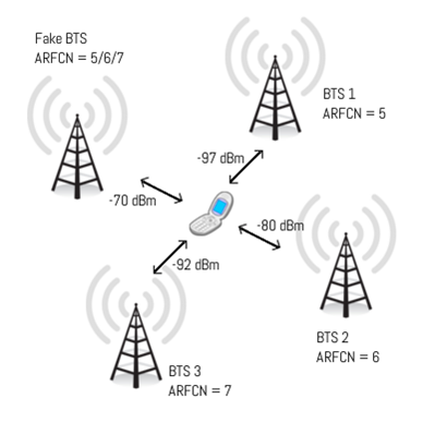
Picture 12. Fake BTS (IMSI catcher) illustration.
After the victim's mobile phone is connected to the fake BTS, the attacker then could send a payload using the Over-the-Air (OTA) method that is common for GSM networks and direct the payload to the smartcard inside the mobile phone.
Conclusion
From the explanation above, we can conclude that an attacker who could exploit a vulnerability on smartcard would result in a catastrophic event, especially if it's related to a critical infrastructure, such as a SCADA installation that utilizes GSM networks or financial institution that utilize GSM networks for their mobile banking. In order to prevent such an attack on a smartcard, vendors could implement some protection, such as developing custom EEPROM for java card.
References
-
ISO/IEC 7816.
(http://en.wikipedia.org/wiki/ISO/IEC_7816)
-
Java Card.
(http://en.wikipedia.org/wiki/Java_Card)
FREE role-guided training plans
-
Java Card Technology from Oracle.
(http://www.oracle.com/technetwork/java/embedded/javacard/overview/index-jsp-140503.html)
-
ETSI TS 100 977, TS 101 267, TS 102 221, TS 102 223, EN 302 409.

- 12 pre-built training plans
- Employer-requested skills
- Personalized, hands-on training
In this Series
- Introduction to Smartcard Security
- Free Valentine's Day cybersecurity cards: Keep your love secure!
- How to design effective cybersecurity policies
- What is attack surface management and how it makes the enterprise more secure
- Is a cybersecurity boot camp worth it?
- The aftermath: An analysis of recent security breaches
- Understanding cybersecurity breaches: Types, common causes and potential risks
- Breaking the Silo: Integrating Email Security with XDR
- What is Security Service Edge (SSE)?
- Cybersecurity in Biden’s era
- Password security: Using Active Directory password policy
- Inside a DDoS attack against a bank: What happened and how it was stopped
- Inside Capital One’s game-changing breach: What happened and key lessons
- A DevSecOps process for ransomware prevention
- What is Digital Risk Protection (DRP)?
- How to choose and harden your VPN: Best practices from NSA & CISA
- Will immersive technology evolve or solve cybercrime?
- Twitch and YouTube abuse: How to stop online harassment
- Can your personality indicate how you’ll react to a cyberthreat?
- The 5 biggest cryptocurrency heists of all time
- Pay GDPR? No thanks, we’d rather pay cybercriminals
- Customer data protection: A comprehensive cybersecurity guide for companies
- Online certification opportunities: 4 vendors who offer online certification exams [updated 2021]
- FLoC delayed: what does this mean for security and privacy?
- Stolen company credentials used within hours, study says
- Don’t use CAPTCHA? Here are 9 CAPTCHA alternatives
- 10 ways to build a cybersecurity team that sticks
- Verizon DBIR 2021 summary: 7 things you should know
- 2021 cybersecurity executive order: Everything you need to know
- Kali Linux: Top 5 tools for stress testing
- Android security: 7 tips and tricks to secure you and your workforce [updated 2021]
- Mobile emulator farms: What are they and how they work
- 3 tracking technologies and their impact on privacy
- In-game currency & money laundering schemes: Fortnite, World of Warcraft & more
- Quantitative risk analysis [updated 2021]
- Understanding DNS sinkholes - A weapon against malware [updated 2021]
- Python for network penetration testing: An overview
- Python for exploit development: Common vulnerabilities and exploits
- Python for exploit development: All about buffer overflows
- Python language basics: understanding exception handling
- Python for pentesting: Programming, exploits and attacks
- Increasing security by hardening the CI/CD build infrastructure
- Pros and cons of public vs internal container image repositories
- CI/CD container security considerations
- Vulnerability scanning inside and outside the container
- How Docker primitives secure container environments
- Top 4 Zapier security risks
- Common container misconfigurations and how to prevent them
- Building container images using Dockerfile best practices
- Securing containers using Docker isolation
- Introduction to container security

Get certified and advance your career
- Exam Pass Guarantee
- Live instruction
- CompTIA, ISACA, (ISC)², Cisco, Microsoft and more!

General security
Free Valentine's Day cybersecurity cards: Keep your love secure!

General security
General security