Gaining Shell Access via UART Interface Part 1

What is IoT
The Internet of Things (IoT) is the network of physical devices, vehicles, home, appliances, vehicle, and other items embedded with electronics, software, sensors, actuators, and connectivity which enables these objects to connect and exchange data.
A word on IoT Security
IoT is the next big technology which will change the way we communicate and exchange data among each other. Every day thousands of IoT devices are coming into the market, the majority of which collect, share, and exchange data among each other. Due to lack of security awareness and guideline/standards to be followed, the majority of IoT Devices are inherently insecure and pose a real threat to the people. Thus, understanding and learning the security of IoT device is of utmost importance.

What should you learn next?
In a nutshell, securing an IoT Network involves securing following interfaces –
- Web Application Interface
- Mobile Application Interface
- Cloud Interface
- Secure Protocol Implementation – Protocols like Bluetooth, Zigbee, CoAP, MQTT, etc.
- Hardware Interface – UART, JTAG, SPI, I2C
Since all the interfaces cannot be discussed in a single post, I am restricting this post to UART. We will also see how one can gain shell access of an IoT Device by exploiting UART.
Types of Hardware communication
At the Hardware level, the device communicates and exchanges data with each other in 2 ways – Serial or Parallel Communication.
In Serial Communication, 1 bit of data is transferred at a time. Example –USB, Ethernet, etc. They all use serial communication for sending and receiving the data.
In Parallel Communication a block of data is transferred at a time. In parallel communication, each bit of data requires a separate line for sending the data. Since each bit is transmitted on a separate channel, parallel communication takes more space than serial communication.
Thus, serial communication is widely used in embedded devices since they take less space, unlike parallel communication.
What is UART
UART stands for Universal Asynchronous Receiver/Transmitter. It's a serial communication protocol. Since UART is Asynchronous, it does not make use of clock for communication with another device. Thus, extra care is taken while transferring the data asynchronously for minimizing the packet loss. So how do two devices communicate using UART? It is done using Baud Rate. More on Baud Rate later.
Sample UART pin is shown below marked in Red
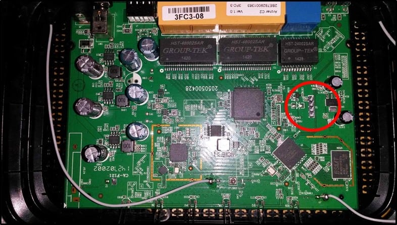
It has four pins –
- Tx – Tx is used for transmitting the data from one device to another device
- Rx – Rx is used for receiving the data from one device to another device
- Vcc – Voltage Pin. It's usually either 3.3V or 5V
- GND – Ground Pin
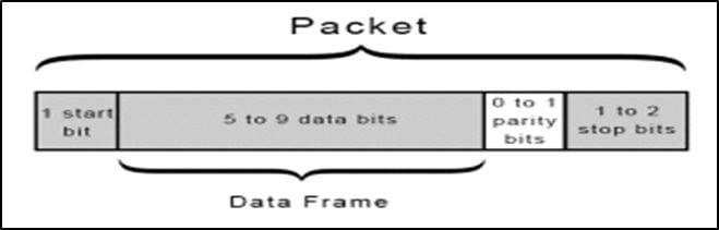
UART Data Packet Structure –
UART transmitted data is organized into packets. Each packet contains -
- 1 start bit
- 5-9 data bits
- Parity bit (Optional)
- 1-2 stop bits
Let's understand UART packet in detail -
- START BIT – This is the first bit in any UART packet and the size is of 1 bit.
When no transmission is happening on the UART line, the UART data transmission line is normally held at a high voltage level. The transfer of data is initiated by pulling the transmission line from high to low. This happens for 1 clock cycle. When the receiving line sees voltage transition from high to low, it starts reading the data in the data frame at a particular baud rate. I will discuss Baud Rate in next part - DATA FRAME – After start bit, comes Data Frame. It contains the actual data to be transferred or transmitted. It can be 5-8 bits long, if a parity bit is used. If no parity bit is used, the data frame is 9 bits long.
- PARITY - After Data Frame, comes Parity Bit. This bit describes the evenness or oddness of a number. The parity bit is one of the ways for the receiving UART to tell if any data has changed during transmission. Bits can be changed due to electromagnetic radiation, long distance data transfers or mismatched baud rates. After receiving the data frame, receiving UART counts a number of 1's in the date frame checks whether the total is even or odd number. If the parity bit is 0, the no. of 1's should be an even number else the no. of 1's should be an odd number. If this isn't the case, UART comes to know that the bits have changed and is corrupt.
- STOP BITS - Stop Bit is the last bit in the UART Packet. The sending UART changes the transmission line from low voltage to high voltage for indicating the end of the transmission line.
UART ADVANTAGES AND DISADVANTAGES
Advantages –
- Uses two wires
- No clock signal needed.
- Parity Bit for error checking
- Widely Used.
Disadvantages –
- Data frame size is limited to 9 bits.
- No support for multiple slave or master
That's it for this post. In the next part, we will look at other technicalities of UART and tools required for Pentesting UART communication.
References –
https://en.wikipedia.org/wiki/Internet_of_things
http://www.flupzor.nl/2015/05/07/uart_on_ac750.html
What should you learn next?

- 12 pre-built training plans
- Employer-requested skills
- Personalized, hands-on training
In this Series
- Gaining Shell Access via UART Interface Part 1
- Intelligence-led pentesting and the evolution of Red Team operations
- Red Teaming: Taking advantage of Certify to attack AD networks
- How ethical hacking and pentesting is changing in 2022
- Ransomware penetration testing: Verifying your ransomware readiness
- Red Teaming: Main tools for wireless penetration tests
- Fundamentals of IoT firmware reverse engineering
- Red Teaming: Top tools and gadgets for physical assessments
- Red teaming: Initial access and foothold
- Top tools for red teaming
- What is penetration testing, anyway?
- Red Teaming: Persistence Techniques
- Red Teaming: Credential dumping techniques
- Top 6 bug bounty programs for cybersecurity professionals
- Tunneling and port forwarding tools used during red teaming assessments
- SigintOS: Signal Intelligence via a single graphical interface
- Top tools for mobile android assessments
- Top tools for mobile iOS assessments
- Red Team: C2 frameworks for pentesting
- Inside 1,602 pentests: Common vulnerabilities, findings and fixes
- Red teaming tutorial: Active directory pentesting approach and tools
- Red Team tutorial: A walkthrough on memory injection techniques
- Python for active defense: Monitoring
- Python for active defense: Network
- Python for active defense: Decoys
- How to write a port scanner in Python in 5 minutes: Example and walkthrough
- Using Python for MITRE ATT&CK and data encrypted for impact
- Explore Python for MITRE ATT&CK exfiltration and non-application layer protocol
- Explore Python for MITRE ATT&CK command-and-control
- Explore Python for MITRE ATT&CK email collection and clipboard data
- Explore Python for MITRE ATT&CK lateral movement and remote services
- Explore Python for MITRE ATT&CK account and directory discovery
- Explore Python for MITRE ATT&CK credential access and network sniffing
- Top 10 security tools for bug bounty hunters
- Kali Linux: Top 5 tools for password attacks
- Kali Linux: Top 5 tools for post exploitation
- Kali Linux: Top 5 tools for database security assessments
- Kali Linux: Top 5 tools for information gathering
- Kali Linux: Top 5 tools for sniffing and spoofing
- Kali Linux: Top 8 tools for wireless attacks
- Kali Linux: Top 5 tools for penetration testing reporting
- Kali Linux overview: 14 uses for digital forensics and pentesting
- Top 19 Kali Linux tools for vulnerability assessments
- Explore Python for MITRE ATT&CK persistence
- Explore Python for MITRE ATT&CK defense evasion
- Explore Python for MITRE ATT&CK privilege escalation
- Explore Python for MITRE ATT&CK initial access
- Top 18 tools for vulnerability exploitation in Kali Linux
- Explore Python for MITRE PRE-ATT&CK, network scanning and Scapy
- Kali Linux: Top 5 tools for social engineering
- Basic snort rules syntax and usage [updated 2021]

Get certified and advance your career
- Exam Pass Guarantee
- Live instruction
- CompTIA, ISACA, (ISC)², Cisco, Microsoft and more!

Penetration testing
Intelligence-led pentesting and the evolution of Red Team operations

Penetration testing
Red Teaming: Taking advantage of Certify to attack AD networks
Penetration testing
Penetration testing
Ransomware penetration testing: Verifying your ransomware readiness